Difference between revisions of "RAID"
| (20 intermediate revisions by 3 users not shown) | |||
| Line 5: | Line 5: | ||
Hospitals, Call Support Centers and any organization that strives to provide the highest level of customer service and shave-off possible down-time will find RAID indispensible. | Hospitals, Call Support Centers and any organization that strives to provide the highest level of customer service and shave-off possible down-time will find RAID indispensible. | ||
| − | IPitomy RAID is available in software | + | IPitomy RAID is available in a software variation to allow its deployment onto the smallest system configuration. |
Software RAID can be implemented on any platform and delivers the basis of RAID security. RAID status is presented to the user/dealer via the Standard IPitomy software interface. | Software RAID can be implemented on any platform and delivers the basis of RAID security. RAID status is presented to the user/dealer via the Standard IPitomy software interface. | ||
| − | |||
| − | |||
RAID is configured at IPitomy and shipped as a complete product solution. It is not available as a field upgrade. | RAID is configured at IPitomy and shipped as a complete product solution. It is not available as a field upgrade. | ||
| Line 53: | Line 51: | ||
| Yes | | Yes | ||
|} | |} | ||
| − | |||
| − | |||
== RAID Configurations / Redundancy Options == | == RAID Configurations / Redundancy Options == | ||
| Line 91: | Line 87: | ||
== Procedure == | == Procedure == | ||
| − | Since the RAID options are installed at IPitomy no user servicing is required to install RAID. | + | Since the RAID options are installed at IPitomy no user servicing is required to install RAID.This procedure guides the service technician through restoring a system to RAID protected status when a Degraded Array (failure) has occurred.(In RAID-1 data is stored on multiple drives (an Array) as a single drive.)[[File:RAID-clean.png|right]] |
| − | |||
In the screen shot the PBX is reporting<span style="font-size: 12px;">: </span> | In the screen shot the PBX is reporting<span style="font-size: 12px;">: </span> | ||
| − | “RAID Status: | + | “RAID Status: clean”. |
This screen capture is from: '''<span style="font-size: 12px;">PBX Setup/Services/</span>''' | This screen capture is from: '''<span style="font-size: 12px;">PBX Setup/Services/</span>''' | ||
| + | <br><br><br><br><br><br> | ||
| + | |||
| + | |||
| + | When a failure occurs the displayed information will show which drive has failed. | ||
| + | |||
| + | This screen (from PBX Setup/Services/) shows that Drive 1 has failed. A failure is denoted by the word “degraded” in the RAID Status display. | ||
| + | [[File:RAID-failed.png|right]] | ||
| + | <br><br><br><br><br><br> | ||
| + | |||
| + | Try clicking the Rebuild button and allow the system to recover the other drive. This may take some time, so be patient and allow it to complete. Sometimes you need to power the system down and unplug from the wall before clicking the Rebuild button will work, as the HD may be in a state that requires a removal of power to bring back to a working state. | ||
| + | |||
| + | === RAID - Drive Removal === | ||
| + | #Locate the defective drive in the PBX. | ||
| + | #TAKE Care to remove the correct drive! Using the System Information screen (PBX Setup/Services/)... IDENTIFY the failed drive. In the display the left-most drive is Drive 0, the right-most drive is Drive 1. | ||
| + | #POWER OFF the PBX; this is most efficiently accomplished using the Boot/Power-Down switch on the front panel. It’s a momentary switch and will return to its idle position. | ||
| + | #Press this button on the raised side—it may also be printed with a dot or large “I”. | ||
| + | #Once pressed the PBX will begin it’s power-down sequence. When complete the PBX LED will be OFF. | ||
| + | #At this time you should be wearing a grounded wrist-strap to prevent ESD damage to components inside the PBX. | ||
| + | #If working on IP2000 or greater: Not all power supplies are the same. If your power supply has an ON/OFF switch, move it to the OFF position. Otherwise skip this step. | ||
| + | #Disconnect the power cord at the back of the PBX cabinet. | ||
| + | #Remove the housing cover screws—depending upon the genre of case these vary in location. Usually the case screws are at the sides of the case lid. In some cases there will be a screw at the back as well. | ||
| + | #The case lid must be pushed backward to free it from the front panel mated-lip. Do so and lift the case lid up and off of the housing. | ||
| + | #Inside the PBX, locate the HDD that will be replaced using the next few steps to identify the drive. | ||
| + | #Matching the actual HDD to that in the PBX Setup/Services displayed is done by tracing the wire from the corresponding port to the HDD. | ||
| + | #In the photos, the HDD connectors on the PBX Motherboard are labeled “SATA 0” and “SATA 1” to assist in this identification. | ||
| + | #If your version of PBX SW supports serial number identification—use that number to ID the HDD and skip to Step 18. Otherwise continue to ID the defective HDD with Step 17. | ||
| + | #Using the wire connected to the SATA port associated to the defective HDD, locate the drive that is to be removed. | ||
| + | #Disconnect the SATA cable and power cable from the HDD. | ||
| + | #Use standard PC hardware tools to remove the HDD from the chassis. | ||
| + | #Replace the HDD. It is best to match the HDD that is being replaced. If this is not possible, get a replacement HDD with similar specifications and storage capacity. You must match or exceed the storage capacity to assure capacity is available for RAID storage. RAID will configure the media installed to the extent of the smallest capacity HDD. Use a new drive. A drive from another source—particularly another RAID-enabled system may be recognized as the data SOURCE! This can result in complete loss of existing data! | ||
| + | #Install the new HDD using the hardware supplied with the drive. | ||
| + | #Connect the SATA cable and power cable to the drive. | ||
| + | #Use cable ties and secure the wiring so that it cannot become pinched when the chassis cover is replaced. Also assure that wiring does not obstruct fan blades. | ||
| + | #Replace the chassis lid making sure to position the front edge under the housing front mated lip and secure with the screws previously removed. | ||
| + | #Continue to Software RAID Restore Procedure. | ||
| + | |||
| + | === RAID - Restore === | ||
| + | |||
| + | When the HDD has been replaced the RAID Array must be rebuilt so that RAID redundancy is restored. The steps here assume that the HDD has been replaced. If not, return to the previous Procedures to replace the defective drive, then return here to restore RAID functionality. This procedure requires the use of an ancillary (spare) Keyboard and monitor. | ||
| + | |||
| + | #With the new HDD installed and the chassis case closed, restore power to the PBX. | ||
| + | #Reconnect the power cable to the PBX. | ||
| + | #Not all power supplies are the same. If your PBX PS has an On/Off switch, move it to the ON position. | ||
| + | #Use the Boot-Up/Power-Down button on the front panel to start the PBX. | ||
| + | #this button on the raised side, it may also be printed with a dot or large “I”. It is a momentary switch and will return to its idle position. | ||
| + | #When the PBX has booted, log into the PBX Administration GUI (web page). | ||
| + | #Navigate to the PBX Setup/Services/ page. You should see a screen similar to this: | ||
| − | + | [[File:RAID-failed.png|center|RAID-failed.png]] | |
| + | <ol start="8"> | ||
| + | <li>Click on the “Rebuild Array” button to start the Array rebuilding process. Note: this process will continue in the background while the PBX is operation. Depending on PBX activity and HDD size and source content the time required to rebuild the Array will vary. Fortunately you don’t have to wait… this process will continue in the background while the PBX is running. Progress can be reviewed at this same page (via percent complete notation):</li> | ||
| + | </ol> | ||
| − | + | [[File:RAID-recovering.PNG|center|RAID-recovering.PNG]] | |
| − | |||
| − | |||
| − | |||
| − | |||
| − | |||
| − | |||
| − | |||
| − | |||
| − | |||
| − | < | + | <b>Note: Do NOT interrupt power while rebuilding the Array </b> |
Latest revision as of 18:01, 26 August 2014
Description
IPitomy now delivers RAID-1 on all platforms of the IPitomy IP PBX.RAID is “Redundant Array of Independent Disks”. RAID-1 is the mirroring of data onto two or more independent Hard Disk Drives. (HDD-Array) (Two HDD’s maximum in IP1100 and IP1200.)
Hospitals, Call Support Centers and any organization that strives to provide the highest level of customer service and shave-off possible down-time will find RAID indispensible.
IPitomy RAID is available in a software variation to allow its deployment onto the smallest system configuration.
Software RAID can be implemented on any platform and delivers the basis of RAID security. RAID status is presented to the user/dealer via the Standard IPitomy software interface.
RAID is configured at IPitomy and shipped as a complete product solution. It is not available as a field upgrade.
| RAID related Features | IP1100 | IP1200 | IP2000 | IP5000 |
| Mirroring Hard Disks (2x) | RAID | RAID | RAID | RAID |
| Automatic Redundancy | RAID | RAID | RAID | RAID |
| Hot Swappaple Hard Drive | No | No | Yes | Yes |
| Front Panel Hard Drive Access | No | No | Yes | Yes |
| Dual Power Supply | No | No | Yes | Yes |
RAID Configurations / Redundancy Options
| Product | Description | Part Number |
| RAID |
Add software RAID for Redundant Hard Drive mirroring. If one drive fails, the other takes over automatically reducing downtime due to drive failure and ensuring a more reliable performance. |
SW-RAID |
| Redundant Power Supply |
4U power supply for IP2000/5000 with two independent replaceable hot swappable power supplies contained in one unit.
|
REDPS |
| SATA Front Loading Rack |
Front Cabinet Accessible Mobile Rack for SATA Drives - Add to IP2000 Chassis as an Option. Should order 2 units for both mirrored SATA drives so both drives will be accessible. This is only an option on the IP2000 chassis. This unit is included in the IP5000 and IP2000-E Chassis |
KF-91 |
Procedure
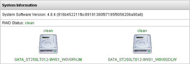
Since the RAID options are installed at IPitomy no user servicing is required to install RAID.This procedure guides the service technician through restoring a system to RAID protected status when a Degraded Array (failure) has occurred.(In RAID-1 data is stored on multiple drives (an Array) as a single drive.)
In the screen shot the PBX is reporting:
“RAID Status: clean”.
This screen capture is from: PBX Setup/Services/
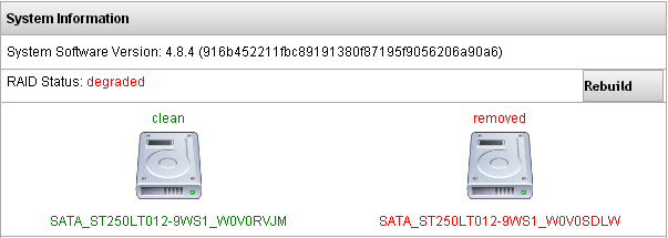
When a failure occurs the displayed information will show which drive has failed.
This screen (from PBX Setup/Services/) shows that Drive 1 has failed. A failure is denoted by the word “degraded” in the RAID Status display.
Try clicking the Rebuild button and allow the system to recover the other drive. This may take some time, so be patient and allow it to complete. Sometimes you need to power the system down and unplug from the wall before clicking the Rebuild button will work, as the HD may be in a state that requires a removal of power to bring back to a working state.
RAID - Drive Removal
- Locate the defective drive in the PBX.
- TAKE Care to remove the correct drive! Using the System Information screen (PBX Setup/Services/)... IDENTIFY the failed drive. In the display the left-most drive is Drive 0, the right-most drive is Drive 1.
- POWER OFF the PBX; this is most efficiently accomplished using the Boot/Power-Down switch on the front panel. It’s a momentary switch and will return to its idle position.
- Press this button on the raised side—it may also be printed with a dot or large “I”.
- Once pressed the PBX will begin it’s power-down sequence. When complete the PBX LED will be OFF.
- At this time you should be wearing a grounded wrist-strap to prevent ESD damage to components inside the PBX.
- If working on IP2000 or greater: Not all power supplies are the same. If your power supply has an ON/OFF switch, move it to the OFF position. Otherwise skip this step.
- Disconnect the power cord at the back of the PBX cabinet.
- Remove the housing cover screws—depending upon the genre of case these vary in location. Usually the case screws are at the sides of the case lid. In some cases there will be a screw at the back as well.
- The case lid must be pushed backward to free it from the front panel mated-lip. Do so and lift the case lid up and off of the housing.
- Inside the PBX, locate the HDD that will be replaced using the next few steps to identify the drive.
- Matching the actual HDD to that in the PBX Setup/Services displayed is done by tracing the wire from the corresponding port to the HDD.
- In the photos, the HDD connectors on the PBX Motherboard are labeled “SATA 0” and “SATA 1” to assist in this identification.
- If your version of PBX SW supports serial number identification—use that number to ID the HDD and skip to Step 18. Otherwise continue to ID the defective HDD with Step 17.
- Using the wire connected to the SATA port associated to the defective HDD, locate the drive that is to be removed.
- Disconnect the SATA cable and power cable from the HDD.
- Use standard PC hardware tools to remove the HDD from the chassis.
- Replace the HDD. It is best to match the HDD that is being replaced. If this is not possible, get a replacement HDD with similar specifications and storage capacity. You must match or exceed the storage capacity to assure capacity is available for RAID storage. RAID will configure the media installed to the extent of the smallest capacity HDD. Use a new drive. A drive from another source—particularly another RAID-enabled system may be recognized as the data SOURCE! This can result in complete loss of existing data!
- Install the new HDD using the hardware supplied with the drive.
- Connect the SATA cable and power cable to the drive.
- Use cable ties and secure the wiring so that it cannot become pinched when the chassis cover is replaced. Also assure that wiring does not obstruct fan blades.
- Replace the chassis lid making sure to position the front edge under the housing front mated lip and secure with the screws previously removed.
- Continue to Software RAID Restore Procedure.
RAID - Restore
When the HDD has been replaced the RAID Array must be rebuilt so that RAID redundancy is restored. The steps here assume that the HDD has been replaced. If not, return to the previous Procedures to replace the defective drive, then return here to restore RAID functionality. This procedure requires the use of an ancillary (spare) Keyboard and monitor.
- With the new HDD installed and the chassis case closed, restore power to the PBX.
- Reconnect the power cable to the PBX.
- Not all power supplies are the same. If your PBX PS has an On/Off switch, move it to the ON position.
- Use the Boot-Up/Power-Down button on the front panel to start the PBX.
- this button on the raised side, it may also be printed with a dot or large “I”. It is a momentary switch and will return to its idle position.
- When the PBX has booted, log into the PBX Administration GUI (web page).
- Navigate to the PBX Setup/Services/ page. You should see a screen similar to this:
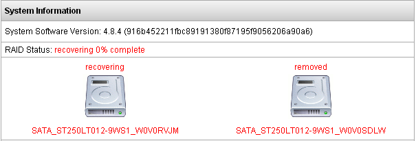
- Click on the “Rebuild Array” button to start the Array rebuilding process. Note: this process will continue in the background while the PBX is operation. Depending on PBX activity and HDD size and source content the time required to rebuild the Array will vary. Fortunately you don’t have to wait… this process will continue in the background while the PBX is running. Progress can be reviewed at this same page (via percent complete notation):
Note: Do NOT interrupt power while rebuilding the Array


