IPitomy Monitored Router
The IPitomy Monitored Router will replace the onsite router and allow for monitoring and traffic shaping to optimize VOIP.
Unboxing
Your IPitomy Monitored Router comes with 1 firewall, 1 ethernet cable, and 1 power supply. For installation you need an Internet connection, two ethernet cords, and a network switch.
Whether using the Professional or Advanced unit, the set up process will be the same. The following images illustrate the ports you will use for each type of firewall. Otherwise, all of the steps will remain the same for each installation.
- NOTE:: The device must be provisioned in the Dashboard before continuing. This will most likely have been done by IPitomy during shipping.
Professional
Advanced
Connecting Cables
- For this product to work properly, please make sure your ISP has your modem in Transparent Bridge Mode before proceeding. Some modems require a reboot when connecting a new device.
- Plug your Internet connection coming from your modem (Cable/DSL) or Ethernet (Fiber/T1) in the WAN Port "A". Connect your PC direct to LAN Port "B".
- Connect your Power Supply to Port "C".
- The OPT Port "D" is for an optional failover secondary Internet connection.
- NOTE::After the device is connected and powered on, you will need to reboot the computer or release and renew so it pulls a new IP address from the IPitomy Monitored Router.
Testing
If the public IP of the site is dynamic, you should be able to get out to the internet after 1-2 minutes. You can test this by going to www.google.com. This will result in a testing screen if it succeeds in getting its WAN IP via DHCP, or a Failed to Detect Screen.
If you see the testing screen, wait 1-2 minutes, once its finish, you will be connected to www.google.com, you are finished and can now connect the sites network switch to the LAN Port "B".
If you get the Failed to Detect Screen, you will need some basic information from your ISP.
- Your Static IP Address, Subnet Mask, and Gateway
OR
- PPOE/PPTP Username and Password
Input this information and save.
- NOTE:: If you input information on this screen and it successfully connects, the information will be saved to the dashboard on completion. You should not have to enter this information again. After you have saved, go back to your browser and go to www.google.com The testing page will now come up; wait 2-3 minutes. When Google comes up, you are online and can connect the LAN Port "B" to the sites network switch.
Front Light Key
- 1 Solid Light: Unit Has Power
- 2 Solid Lights: The Internet has been detected
- 1 Solid Light, 1 Flashing Light: Testing Internet connection in progress
- 3 Solid Lights: System is up and operational
Programming
Once the router is connected out to the internet, it will download its programming from the cloud. To access the cloud and program it, head to https://ipitomy.mycloudconnection.com. Choose Dashboard Login and you will login as a User with the Username and Password provided to you.
Firewall and Port Forwarding
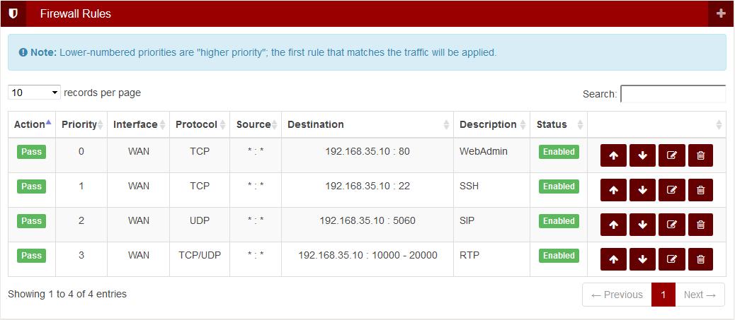
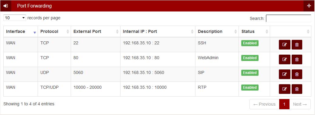
In order to program the router to allow traffic inbound from the outside to the LAN, you need to create a Firewall Rule and Port Forwarding. Below are examples of how to set this up for the standard ports of 80, 22, 5060, and 10k-20k. You can use these examples to create any other port forwarding and firewalls your customer may need. (In these examples the PBX was at 192.168.35.10)


