Difference between revisions of "IP PBX Manual System Networking"
| (9 intermediate revisions by the same user not shown) | |||
| Line 1: | Line 1: | ||
__NOTITLE__ | __NOTITLE__ | ||
{{IP_PBX_Manual|sortkey=System Networking}} | {{IP_PBX_Manual|sortkey=System Networking}} | ||
| − | = '''System Networking'''<br/> = | + | == '''System Networking'''<br/> == |
The IPitomy System Menu is for configuring network attributes. For example the IP address of the system and router information. The System Networking Setup Page allows you to define the Internet Setup for the system’s hardware. The system must operate using a static IP address; DHCP should only be used on the IPitomy IP PBX if the router is configured to assign a specific static DHCP address to the system. [[File:Tcpipsettings.png|center|Tcpipsettings.png]]<br/>The following table describes the fields and recommended settings for Networking Setup for the IP PBX system: | The IPitomy System Menu is for configuring network attributes. For example the IP address of the system and router information. The System Networking Setup Page allows you to define the Internet Setup for the system’s hardware. The system must operate using a static IP address; DHCP should only be used on the IPitomy IP PBX if the router is configured to assign a specific static DHCP address to the system. [[File:Tcpipsettings.png|center|Tcpipsettings.png]]<br/>The following table describes the fields and recommended settings for Networking Setup for the IP PBX system: | ||
| Line 51: | Line 51: | ||
#Click on the '''Save Changes''' button | #Click on the '''Save Changes''' button | ||
#Click the '''Apply Changes''' link located on the right hand corner of the page, to commit the changes to the database. | #Click the '''Apply Changes''' link located on the right hand corner of the page, to commit the changes to the database. | ||
| + | |||
| + | == VLAN == | ||
| + | {{:VLAN}} | ||
== Access Control (PBX Access)<br/> == | == Access Control (PBX Access)<br/> == | ||
| Line 154: | Line 157: | ||
#Navigate to the '''Access Control List''' page, click '''Load Recommended Default''' button. This will create default rules allowing the PBX to communicate to devices on the LocalNet in regards to SIP, Call Manager, and TFTP | #Navigate to the '''Access Control List''' page, click '''Load Recommended Default''' button. This will create default rules allowing the PBX to communicate to devices on the LocalNet in regards to SIP, Call Manager, and TFTP | ||
#Click the '''Apply Changes''' link located on the right hand corner of the page, to commit the changes to the database. | #Click the '''Apply Changes''' link located on the right hand corner of the page, to commit the changes to the database. | ||
| + | [[File:Load defaults.png|none|frame]] | ||
=== Add New Service === | === Add New Service === | ||
| Line 257: | Line 261: | ||
To add an IP to the list, enter <ipaddress>/<subnetmask> in the text field and click add. Highlight an entry and click Delete to remove it from the list. As always, you must Save first, then Apply Changes for these features to become active on the live system. | To add an IP to the list, enter <ipaddress>/<subnetmask> in the text field and click add. Highlight an entry and click Delete to remove it from the list. As always, you must Save first, then Apply Changes for these features to become active on the live system. | ||
| + | |||
| + | == UI Users & Admin Groups == | ||
| + | |||
| + | With Users and Groups, you the admin can give a user access to the programming side of the PBX and customize what they are able to modify, create, or delete. | ||
| + | |||
| + | === Groups === | ||
| + | |||
| + | Start by adding a Group that will define what features the user is able to edit. You need to set a Group ID (number) and Group Name. | ||
| + | |||
| + | [[File:AdminGroups.jpg|File:AdminGroups.jpg]] | ||
| + | |||
| + | Once created you will need to Edit and choose what features on the PBX the user is able to control. For each feature, you can choose Create, Modify, Delete, as well as filter. Separate multiple filters of the same feature with commas. Filters can be used on Extensions, Groups, Menus, and Conferences. | ||
| + | |||
| + | [[File:AdminGroupsEdit.jpg|File:AdminGroupsEdit.jpg]] | ||
| + | |||
| + | === Users === | ||
| + | |||
| + | Once a Group is created, you can add Users. To do so, you'll need to give them a Username and Password, enter the Name to know which person this User was created for, and set them to a Group. Once created, if you need to modify a field for a User, simply populate the Username field and whichever fields you wish to change, then click Save. The username must be a minimum of 4 characters, or it will create the entry, and then give a bad username or password error when you attempt to log in. | ||
| + | |||
| + | [[File:AdminUsers.jpg|File:AdminUsers.jpg]] | ||
Latest revision as of 13:08, 22 April 2022

System Networking
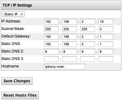
The IPitomy System Menu is for configuring network attributes. For example the IP address of the system and router information. The System Networking Setup Page allows you to define the Internet Setup for the system’s hardware. The system must operate using a static IP address; DHCP should only be used on the IPitomy IP PBX if the router is configured to assign a specific static DHCP address to the system.
The following table describes the fields and recommended settings for Networking Setup for the IP PBX system:
| IP Address | Use the default address (192.168.1.249) of the IPitomy IP PBX or an address outside the range of existing IP addresses assigned by DHCP in the router. The PBX will be accessed via <IPAddress>/ippbx, so at default you would go to 192.168.1.249/ippbx. |
| Subnet Mask | Leave the default setting for the Subnet Mask as (255.255.255.0). The subnet mask defines what traffic the PBX will listen and communicate to. A value of 255 means the octet in question needs to match exactly, while a value of 0 means the octet is not restricted at all. When the PBX is set to the default IP address, a subnet mask of 255.255.255.0 tells the system to communicate with any devices in the 192.168.1.xxx range. |
| Default Gateway | The default gateway provided is 192.168.1.1. Though this default is a common router IP, every network is different. Enter the IP address of the router handling their Internet connection here. |
| Static DNS | Enter the DNS IP address being used on the network. If a default DNS IP address is not provided by the router it can be obtained from the network’s Internet Service Provider. |
| Static DNS2 | Enter the DNS IP address being used on the network. If a default DNS IP address is not provided by the router it can be obtained from the network’s Internet Service Provider. |
| Static DNS3 | Enter the DNS IP address being used on the network. If a default DNS IP address is not provided by the router it can be obtained from the network’s Internet Service Provider. |
Table 6Network Setting Descriptions
TCP/IP Settings Section
Edit TCP/IP Default Settings
STEPS:
- Navigate to System Networking. The TCP/IP Settings page appears displaying the default values for the following setting:
- IP Address
- Subnet Mask
- Default Gateway
- Static DNS
- Click on the IP Address field. Enter the IP address for the Router. Use the default address (192.168.1.249) of the IPitomy IP PBX or an address outside the range of existing IP addresses assigned by DHCP in the router Enter the desired IP Address. See Table above for recommended settings.
- Click on the Subnet Mask field. Leave the default setting for the Subnet Mask as (255.255.255.0). See Table above for recommended settings.
- Click on the Default Gateway field. Change the default Gateway value to the desired target network. See Table above for recommended settings.
- Click on the Static DNS field. Change the default DNS value to the desired target network. See Table above for recommended settings.
- Repeat step 5 to set the remaining DNS values, if necessary.
- Click on the Save Changes button
- Click the Apply Changes link located on the right hand corner of the page, to commit the changes to the database.
VLAN
Setting up VLAN from the PBX
This guide requires a managed switch and knowledge of how to set up VLANs on it, which is outside of the scope of this guide. This is only to show how to set up VLAN on the pbx, and enable it for all phones. This requires your PBX to be on software version 5.1.5-5 or higher. All network switch ports that will have a phone on it should have its port tagged for the appropriate vlan.
WARNING: DO NOT SET VLAN IP ADDRESS ON THE SAME NETWORK AS STANDARD NETWORK INTERFACE! This will lock up the pbx and cause it to become PERMANENTLY inaccessible. Example, if your standard network is 192.168.1.x, your vlan network CANNOT be the same.
- Define the VLAN under System=>VLAN. It must be enabled.
- Set VLAN IP Address to the IP address that you would like to give the PBX on that vlan, which will also hand out DHCP on the vlan to the phones (This MUST be a different IP address from the main IP address set under system=>networking)
- Set the VLAN Subnet mask to define the network just as you would on standard network settings. 255.255.255.0 is generally going to suffice.
- Set the VID to the actual VLAN ID tag. This must match the VLAN in the switch that you are assigning the ports to.
- Set DHCP Start and End addresses as desired
- Save
NOTE: If your phones are on a vlan, autodiscovery will not find them with the default settings. To scan the vlan network instead of normal network, go to destinations->auto discovery like normal, choose scan or don't scan as desired, and go under View Settings -> Advanced Scan Settings, and change the Scan Network box to the network (CIDR notation) that you wish to scan for the phones.
- Navigate to PBX Setup=Phone Global
- Set Apply VLAN Config to Phones to Enabled
- Set Phone VLAN Enable to Enabled
- Set Phone VID to match VID from step 4 above
- If needed, set PC VLAN settings according to network.
- Save
- Apply changes
- Reboot phones. They should pick up vlan config and be on the vlan network correctly.
This process replaces the need to set vlan in the phone global template. Using the phone global template to assign vlan is no longer necessary as of 5.1.5-5
LLDP
Warning: Do not follow this guide unless you know for certain you need LLDP. Incorrectly implementing this protocol MAY lead to undesired network functionality.
This guide applies to Cisco switches, and the screenshots are specifically from a SG300 28 port switch. Some options may be named differently, or not exist at all on other brands of network equipment.
In the switch:
LLDP Status: Enabled
TLV Advertise Interval: 60
LLDP MED Network Policy
Create 2 policies as follows
Application Voice, VLAN ID 2, VLAN Tagged
Application Voice Signaling, VLAN ID 2, VLAN Tagged
LLDP MED Port Settings
Add Voice and Voice signaling applications to desired ports
VLAN Management=>Voice VLAN=>Properties
Dynamic Voice VLAN: Disabled
Create VLAN: VlanID 2, name Voice
Port to VLAN
Set desired ports for voice traffic (any port that will have a phone plugged in, plus the port that will handle voice dhcp, if needed), to VLAN 2: Tagged
In the PBX
Ensure all phones have LLDP enabled. You can set this on each phone individually in the menu under Settings=>Advanced=>Network=>LLDP, but we would recommend following the instructions listed at http://wiki.ipitomy.com/wiki/HD_Phone_FAQ#How_do_I_Enabled_LLDP_Globally_for_the_Phones to set LLDP globally if you need it for all phones.
Helpful Links
Virtual Local Area Networks (VLANs)
http://www.practicalnetworking.net/stand-alone/vlans/
All Credit and Thanks go to networking guru Ed Harmoush at Practical Networking
Routing Between VLANs
http://www.practicalnetworking.net/stand-alone/routing-between-vlans/
All Credit and Thanks go to networking guru Ed Harmoush at Practical Networking
Access Control (PBX Access)
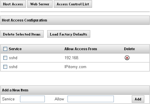
The Access Control page is comprised of 3 sub-pages; Host Access, Web Server, and Access Control List. Each is accessible from the buttons at the top of the page and pertains a different method of controlling access to the PBX.
Host Access
This feature allows you to limit access to special services on the PBX. An “allow from” entry is a list of one or more host names, host addresses, patterns or wildcards that will be matched against the client host name or address. List elements should be separated by blanks and/or commas.
Note: The parameter for the IP PBX Host Access is pre-configured per the manufacturer’s specifications. We recommend that you do not change this configuration value.
The following table describes the features and functions available on the Host Access page:
| Fields/Buttons | |
| Delete Selected Items | This button allows you to delete multiple services at a time. |
| Load Factory Defaults | This button will set the PBX back to the default Host Access settings.
|
| Add a New Item | This section is where you would add new rules for accessing special services on the PBX |
Table 7Network Features and Descriptions
| IMPORTANT: Changes to the Host Access List are installed immediately. They are database independent so custom changes do not migrate from one box to another via a database backup file.
Please contact IPitomy’s Technical Support Group if you think you need to modify these settings. |
Web Server Configuration - (Obsolete - Removed in 4.8.0)
Link to Old Info Web Server Configuration
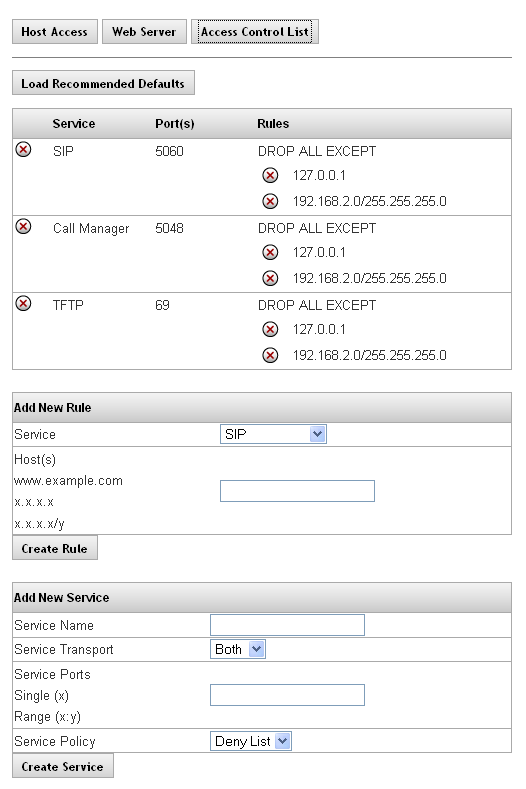
Access Control List
The Access Control List defines what networks different PBX features are permitted to communicate with. This is a security feature that we recommend using. If the site communicates to a SIP provider or Remote Phones, you will need to add their IP address to the list. The SIP Provider should give you either a single static IP or a subnet range (eg. 8.3.42.0/30) to add to allow them inbound. Remote phones with a static IP can have that single address added (eg. 72.64.129.45/32). If the remote phone is at a site with a dynamic IP, go to whois.domaintools.com and lookup that IP, this will give you the subnet of the carrier in that area, add that range as a rule to the SIP ACL (eg. 68.23.0.0/12). The only times I would not be using the SIP ACL is if a user has a softphone on their cell, or if a user travels with their phone to different locationsas you won't have any way to know what IP it would be registering from.
The following table outlines the parameters and descriptions for the Access Control List.
| Feature | |
|
Default |
Displays the name of configured services. Typical services on the PBX are:
SIP: Used for Calls Call Manager: Used for Desktop Call Manager TFTP: Used by phones to pull down config and firmware files |
| Ports | Displays the ports that were defined for a particular service.
SIP: 5060 Call Manager: 5048 TFTP: 69 |
| Rules | Displays the rules that were configured for a particular service.
Deny List: Accepts all traffic, unless specifically defined Allow List: Denies all traffic, unless specifically defined |
Table 9Access Control List Definitions
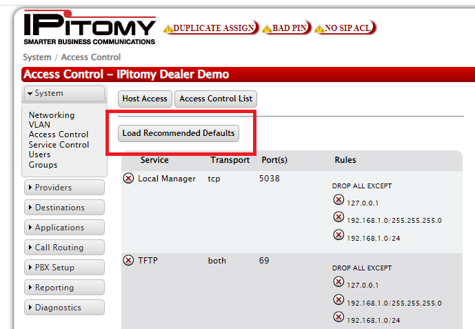
Load Recommended Default
This is the recommended method to set the Access Control List to the typically used settings.
STEPS:
- Navigate to PBX Setup->SIP
- Set the LocalNet to match the network the PBX is installed on, Save, and Apply Changes
- Navigate to the Access Control List page, click Load Recommended Default button. This will create default rules allowing the PBX to communicate to devices on the LocalNet in regards to SIP, Call Manager, and TFTP
- Click the Apply Changes link located on the right hand corner of the page, to commit the changes to the database.
Add New Service
The following table outlines the parameters and descriptions required for adding a new service.
| Feature | |
| Service Name | This is the name of the new service and will populate the Service drop-down list in the Add New Rule section. |
| Service Transport | This is the service type that will be used to transport the message. The options are Both, TCP or UDP.
SIP and RTP traffic both occur on UDP, TFTP traffic is UDP, and Call Manager traffic is TCP. Any other rules created would need to be configured for the protocol used by this service. |
| Service Ports | This is the port information that is associated with the host. You can enter a single or range of ports that will be used for this service. SIP uses 5060, Call Manager uses 5048, and TFTP uses 69. Other services must be configured to use the appropriate ports. |
| Service Policy | This is the umbrella rule for the service, which will be further defined under Add New Rules. The options are:
Deny List: ACCEPT ALL EXCEPT rule will apply. This will allow all traffic on the defined port, allowing you to configure a list of Denied IP addresses. Allow List: DROP ALL EXCEPT rule will apply. This will block all traffic on the defined port, allowing you to configure a list of Allowed IP addresses. |
The following outlines the steps to add a new service in the PBX system.
STEPS:
- Navigate to System->Access Control
- Click on theAccess Control List button, The Access Control List page appears.
- From the Add New Service section, enter a Name, and select the appropriate Transport Protocol, Ports, and Policy; then click the Create Service button.
- The new service and its associated values will be displayed in the Service listing.
- Click the Apply Changes link located on the right hand corner of the page, to commit the changes to the database.
The following table outlines the parameters and descriptions required for adding a new rule.
| Feature | |
| Service | This drop-down list is populated when a new services is added. This is done in the Add New Service section. |
| Host(s) | This is the IP Address, Domain Name or URL of the host. |
Table 11Add New Rule Settings and Descriptions
Add New Rule
The following outlines the steps to add a new rule for Services in the PBX system.
STEPS:
- Navigate to System->Access Control, click on theAccess Control List button, the Access Control List appears.
- From the Add New Rule section, select the Service type from the drop-down list.
- Enter the Host/s to be allowed/denied by the service
- Click the Create Rule button.
- The new rule is added and will be displayed in the rules list.
- Click the Apply Changes link located on the right hand corner of the page, to commit the changes to the database. .
Delete Rules or Services
The following outlines the steps to delete existing rules or services.
STEPS:
- From the Service section of the PBX Access->Access Control List page, find the service or rule that you want to delete.
- Click on the X icon to the left of either the service or rule. The selected item is removed from the list.
- Click the Apply Changes link located on the right hand corner of the page, to commit the changes to the database.
Service Control
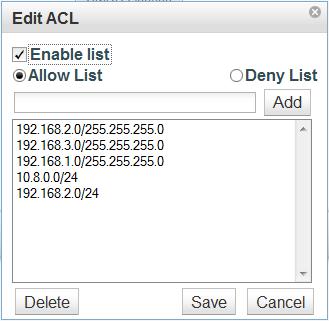
The Service Contol feature allows you to define what networks may communicate to the PBX for Admin Access, Mobile Access, Phone Config Access, SMDR Access, and Web Manager Access.
NOTE: Take care when enabling/modifying the Admin Access ACL as entering the wrong IP or localnet can make it so you are no longer able to access the PBX from the network it is installed upon.
Clicking each of these buttons will bring up a display that allows you to Enable or Disable the ACL, choose if you want it to be an Allow List (block all addresses unless they are in the list) or a Deny List (allow all addresses unless they are on the list), and define the IPs and Subnet Masks to be allowed or denied by the feature.
To add an IP to the list, enter <ipaddress>/<subnetmask> in the text field and click add. Highlight an entry and click Delete to remove it from the list. As always, you must Save first, then Apply Changes for these features to become active on the live system.
UI Users & Admin Groups
With Users and Groups, you the admin can give a user access to the programming side of the PBX and customize what they are able to modify, create, or delete.
Groups
Start by adding a Group that will define what features the user is able to edit. You need to set a Group ID (number) and Group Name.
Once created you will need to Edit and choose what features on the PBX the user is able to control. For each feature, you can choose Create, Modify, Delete, as well as filter. Separate multiple filters of the same feature with commas. Filters can be used on Extensions, Groups, Menus, and Conferences.
Users
Once a Group is created, you can add Users. To do so, you'll need to give them a Username and Password, enter the Name to know which person this User was created for, and set them to a Group. Once created, if you need to modify a field for a User, simply populate the Username field and whichever fields you wish to change, then click Save. The username must be a minimum of 4 characters, or it will create the entry, and then give a bad username or password error when you attempt to log in.
