Training:Install Preparation
Prior to install you should either determine which data switch is to be used, or which are installed already at the site. It is preferred that this be a level 2 managed switch so that QOS can be used to assure high-priority voice traffic handling. The Switch that you use is the primary backbone piece for the network.
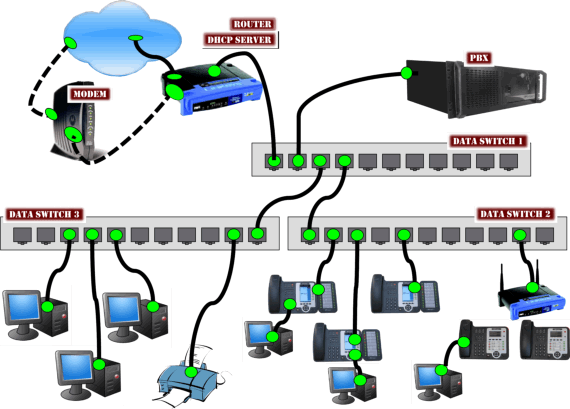
Considerations should be given to the network in terms of configuration and layout. It is common for technicians to make errors in network layout, and in so doing create unnecessary network bottle necks. An example being, if you have 20 phones and they are all plugged into a 24 port switch. It would be most advantageous to plug the PBX into this switch instead of some other piece of gear as this would keep all packets regarding the voice network on the same piece of equipment.
Consideration should also be given to the POE option. Power over Ethernet or PoE technology describes a system to pass electrical power safely, along with data, on Ethernet cabling. The IEEE standard for PoE requires Category 5 cable or higher for high power levels, but can operate with category 3 cable for low power levels. Power is supplied in common mode over two or more of the differential pairs of wires found in the Ethernet cables and comes from a power supply within a PoE-enabled networking device such as an Ethernet switch or can be injected into a cable run with a midspan power supply.
The original IEEE 802.3af-2003 PoE standard provides up to 15.4 W of DC power (minimum 44 V DC and 350 mA) to each device. Only 12.95 W is assured to be available at the powered device as some power is dissipated in the cable.
The updated IEEE 802.3at-2009 PoE standard also known as PoE+ or PoE plus, provides up to 25.5 W of power. The 2009 standard prohibits a powered device from using all four pairs for power. Some vendors have announced products that claim to be compatible with the 802.3at standard and offer up to 51 W of power over a single cable by utilizing all four pairs in the Category 5 cable.
IPitomy telephones consume approximately 7 WATTS of power or less.
Numerous non-standard schemes had been used prior to PoE standardization to provide power over Ethernet cabling. Some are still in active use.
|
Speed [Mbit/s] |
Distance [m] |
Name |
Standard |
Description |
|
1 |
100 (nominally) |
802.3e 1986[9] |
Runs over four wires (two twisted pairs) on telephone twisted pair or Category 3 cable. An active hub sits in the middle and has a port for each node. Manchester coded signaling. | |
|
10 |
100 (nominally) |
(pre) 802.3i 1987 |
Runs over AT&T Premises Distribution System (PDS) wiring or four wires (two twisted pairs) on telephone twisted pair or Category 3 cable.[3][10] | |
|
10 |
100 (nominally)[11] |
10BASE-T |
802.3i 1990 |
Runs over four wires (two twisted pairs) on a Category 3 or Category 5 cable. Star topology with an active hub or switch sits in the middle and has a port for each node. This is also the configuration used for 100BASE-T and gigabit Ethernet. Manchester coded signaling. |
|
100 |
100 |
802.3u 1995 |
4B5B MLT-3 coded signaling, CAT5 copper cabling with two twisted pairs. | |
|
1000 |
100 |
802.3ab 1999 |
PAM-5 coded signaling, At least Category 5 cable, with Category 5e strongly recommended copper cabling with four twisted pairs. Each pair is used in both directions simultaneously. | |
|
10 000 |
100 |
802.3an 2006 |
Uses category 6a cable. |
Installation:
When installing the system it is best to use the following outline:
- Create Extensions
- Import – extensions are created by importing a CSV file
- Auto Discovery - PBX used to discover all phones on the network
- Auto Provision – PBX pairing function to install extensions
- Data Entry - one at a time
- Create Groups
- No limit to Groups
- Use for Department calling patterns
- Ring Strategies to be used
- Queue handling
- Create Menus
- Unlimited Menus
- Use for instructions/announcements
- Use for call routing
- Create Trunks
- SIP – Provider and SIP Configuration known and in-hand
- Hardware
- T-1, PRI
- DID destination
- Default Answering Destination
- Internal Gateway (PBX board for PSTN)
- Default Answering Destination
- T-1, PRI
- Inbound Routing
- Outbound Routing
Test as you go
- configure two phones and then test the connectivity, call between phones and voicemail to test
- configure the balance of the extensions
- When configuring a trunk, set it up and then test prior to full implementation.
- On SIP trunks, configure the trunk and then test inbound and outbound.
- On a PRI to check DID and make sure it is delivered correctly and only then program the balance of the DID’s.
When installing remote phones this method is also advantageous. To verify prior to rollout of all remote phones a single phone should be installed and tested to verify that the port configuration is all accurate.
Once all elements are configured and test correctly then you should proceed with the remainder of the install.
