Training:How does VOIP Work
How Does VoIP Work?
This section provides an introductory overview of Voice over Internet Protocol (VoIP), a technology that enables the transmission of voice communications via IP networks.
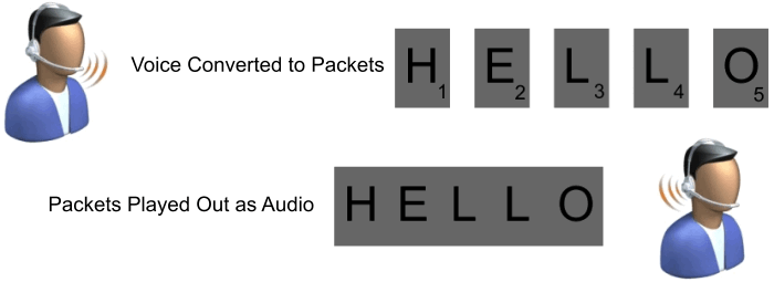
VoIP works on the principle of audio sampling, where a computer records a sound (such as a human voice) at a high rate (typically at least 8,000 times per second) and converts these audio samples into digital data. Unlike traditional recording, where these samples are stored locally, VoIP sends these samples over an IP network to be played back on a different device.
The process of making VoIP function efficiently involves several key steps. Initially, the computer compresses the recorded sound samples to minimize the space they require, focusing particularly on voice frequencies. This compression and decompression process is handled by a tool known as a CODEC (compressor/decompressor). Numerous CODECs are available, and VoIP uses those optimized for voice compression, significantly reducing the bandwidth required compared to uncompressed audio.
After compression, the samples are grouped into larger units and inserted into data packets ready for transmission over the IP network, a process known as packetization. A typical IP packet can contain 10 or more milliseconds of audio, with 20 or 30 milliseconds being the most common.
A comparison could be made to sending postcards through traditional mail. Each postcard (packet) carries a limited amount of information. Sending a lengthy message would require multiple postcards (packets), and to ensure they can be assembled correctly at the destination, they are organized using a sequence number or similar mechanism.
Packets are sometimes delayed, just as with the postcards sent through the post office. This is particularly problematic for VoIP systems, as delays in delivering a voice packet means the information is too old to play. Such old packets are simply discarded, just as if the packet was never received. This is acceptable to a certain degree, as long as the assembled packets do not distort the sound. Too much delay will cause the sound to have less than desirable quality.
IP Devices generally measure the packet delay and expect the delay to remain relatively constant, though delay can increase and decrease during the course of a conversation. Variation in delay is called jitter. Delay, itself, just means it takes longer for the recorded voice spoken by the first person to be heard by the user on the far end. In general, good networks have an end-to-end delay of less than 100ms, though delay up to 400ms is considered acceptable (especially when using satellite systems). Jitter can result in choppy voice or temporary glitches, so VoIP devices implement jitter buffer algorithms to compensate for jitter. Essentially, this means that a certain number of packets are queued before play-out and the queue length may be increased or decreased over time to reduce the number of discarded, late-arriving packets or to reduce "mouth to ear" delay. Such "adaptive jitter buffer" schemes are also used by a wide variety of devices that deal with variable delay.
Jitter in Packet Voice Networks
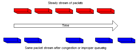
Jitter is defined as a variation in the delay of received packets. At the sending side, packets are sent in a continuous stream with the packets spaced evenly apart. Due to network congestion, improper queuing, or configuration errors, this steady stream can become lumpy, or the delay between each packet can vary instead of remaining constant.
This diagram illustrates how a steady stream of packets is handled.
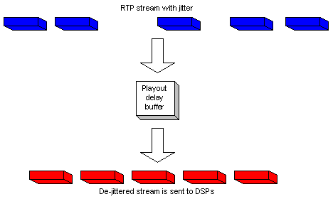
When an IP device receives a Real-Time Protocol (RTP) audio stream for Voice over IP (VoIP), it must compensate for the jitter that is encountered. The mechanism that handles this function is the playout delay buffer. The playout delay buffer must buffer these packets and then play them out in a steady stream to the digital signal processors (DSPs) to be converted back to an analog audio stream. The playout delay buffer is also sometimes referred to as the de-jitter buffer.
This diagram illustrates how jitter is handled.
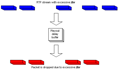
If the jitter is so large that it causes packets to be received out of the range of this buffer, the out-of-range packets are discarded and dropouts are heard in the audio. For losses as small as one packet, the DSP interpolates what it thinks the audio should be and no problem is audible. When jitter exceeds what the DSP can do to make up for the missing packets, audio problems are heard.
This diagram illustrates how excessive jitter is handled.
Video works in much the same way as voice. Video information received through a camera is broken into small pieces, compressed with a CODEC, placed into small packets, and transmitted over the IP network. This is one reason why VoIP is promising as a new technology: adding video or other media is relatively simple. Of course, there are certain issues that must be considered that are unique to video (e.g., frame refresh and much higher bandwidth requirements), but the basic principles of VoIP equally apply to video telephony.
Of course there is much more to VoIP than just sending the audio/video packets over the Internet. There must also be an agreed protocol for how computers find each other and how information is exchanged in order to allow packets to ultimately flow between the communicating devices. There must also be an agreed format (called payload format) for the contents of the media packets.
VoIP is implemented in a variety of hardware devices, including IP phones, analog terminal adapters (ATAs), and gateways. In short, a large number of devices can enable VoIP communication, some of which allow one to use traditional telephone devices to interface with the IP networks.
In a well performing network, VoIP calls should be as clear or clearer that and other type of audio transmissions. VoIP calls are pure digitized sound. Each audio packet contains the pure audio just exactly as it is spoken into the microphone.
High definition voice contains a wider range of frequencies than typical voice transmissions and will deliver surprisingly good audio that contains a richer sound than most toll quality calls.
VoIP Protocols
The success of VoIP communication hinges on employing an appropriate set of protocols. Here, we'll discuss IPitomy SIP Trunking, the preferred protocol for all IPitomy devices currently in circulation as well as many other third-party industry offerings.
The Real-Time Protocol (RTP) is a standard used globally by nearly every device for transmitting audio and video packets between computers. RTP, guided by open standards outlined in various documents, manages issues like packet order and employs mechanisms such as the Real-Time Control Protocol to address delay and jitter.
Before media can flow between two devices, protocols are utilized to locate the remote device and negotiate the media flow methods. These crucial protocols are known as call-signaling protocols, with the Session Initiation Protocol (SIP) being the most widely used.
Advantages of IPitomy SIP Trunks
SIP, a text-based protocol, is relatively straightforward for machines to understand. Its easy readability facilitates troubleshooting by allowing the inspection of packet contents without needing to decompile the software entirely. SIP's operation mirrors that of email, making it familiar and intuitive. Its addressing methods are particularly similar. SIP calls offer undiluted digital voice quality, free of distortion, delay, or echo in its native environment. Instant Scalability: Given IPitomy's IP PBX platform, capacity can be easily adjusted via a simple process in the admin GUI. Interoperability with a wide range of devices provides users with choices far beyond what any single vendor can offer. International dialing is supported. User location is inconsequential; remote users can be deployed globally without losing direct connectivity. An adequate internet connection is the only requirement.
Understanding a SIP Call
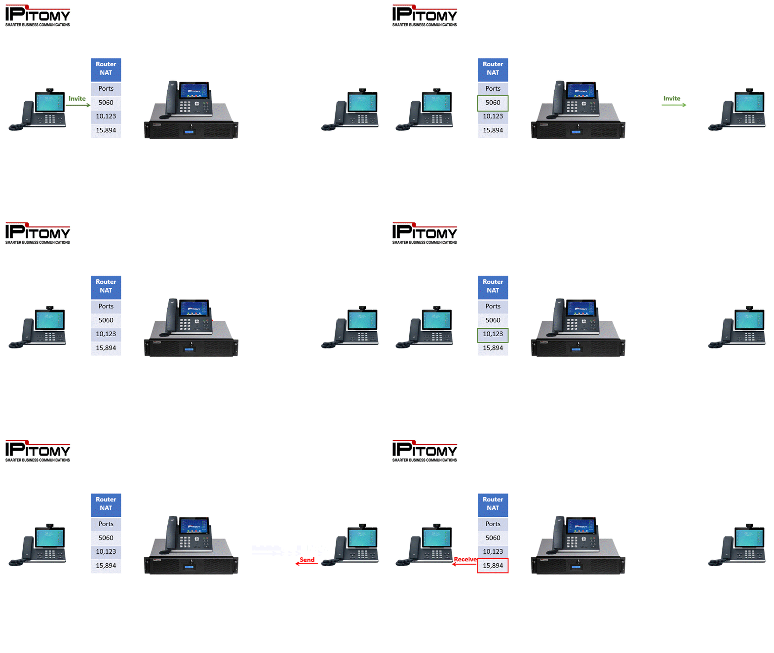
A SIP call comprises a signaling component and a Voice component. The paths for signaling and actual voice transmission differ for each call. Setup and teardown signaling for all calls operate over port 5060. Voice transmissions are conducted within the range of ports 10,000 to 20,000. These are virtual ports integral to TCPIP communication.
Preconditions for a SIP Call
Before a SIP call can occur, SIP endpoints capable of finding and being found by other SIP endpoints are needed. We'll restrict our SIP examples to endpoints that register to an IPitomy IP PBX for this training guide. While peer-to-peer SIP calls are possible, most are facilitated via an IP PBX or soft switch for a PSTN-like ease of dialing. The advantage of an IP PBX is that it simplifies calling another endpoint, allows call information to be stored for reporting, and manages call routing to local and remote extensions. Users dial phone numbers and extension numbers as they would with a legacy PBX system. Although no longer recommended due to their End-Of-Life status, an IPitomy IP PBX still supports analog PSTN lines and T1/PRI cards. SIP endpoints must register with the PBX to be included in the PBX database. Once registered, they can dial phone numbers and receive calls from other endpoints. These endpoints can be phones on the Local Area Network (LAN) or any location on the internet.
Starting a SIP Call
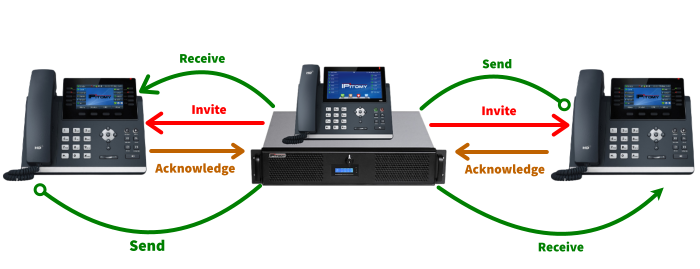
To start a call, the endpoint sends an invite to the server requesting the other endpoint's availability. This occurs on the signaling port (port 5060). If the other endpoint is ready, it sends an acknowledgement back to the initiating phone, which then sends the call information instructing the other phone on the ports to commence the RTP (voice) session. The RTP session is opened using the communicated ports.
Call termination is initiated by one of the endpoints sending a "bye" message, causing the call to hang up. This is a simplified explanation of a SIP call's lifecycle. When the call occurs on the LAN, it bypasses the router. The PBX instructs the endpoints on the ports to connect the RTP (voice) stream.
For calls to remote phones, the PBX understands that the phone is beyond the firewall. Router port configuration becomes necessary for signaling and RTP traffic at this stage.
Signaling Port 5060
Proper port configuration enables port 5060 to be forwarded in the router to the PBX system's LAN IP address, allowing the PBX to send signals to remote phones and receive requests from them.
RTP Ports 10,000 – 20,000 Port Range Forwarding
Once call setup occurs via signaling on Port 5060, RTP is set up using a range of ports forwarded to the PBX LAN IP address. The Port Range Forwarding feature in the Router is used to forward the range of Ports 10,000 – 20,000 for this purpose.
Each call requires two ports for RTP - one for sending and one for receiving. This is organized by the initiating phone. The router ports are open from inside the firewall. The remote phone receives the information about which ports to use from the SIP packets.
Local Phone Diagram
Remote Phone Diagram
Network Address Translation – NAT
TCP/IP, short for Transmission Control Protocol/Internet Protocol, is the underlying communication protocol used for data exchange on the internet. It leverages unique IP addresses to deliver data to the correct device on a network. The types and classes of IP addresses play a crucial role in how data is routed across the internet.
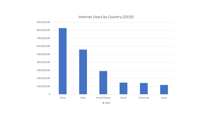
If you're online, odds are you're using Network Address Translation (NAT). This becomes increasingly likely given the growing internet user base. As of 2023, the internet is accessed by nearly 5 billion people worldwide, approximately 63% of the global population. This figure continues to rise, with nearly 200 million new users connecting in the year leading up to April 2023.
So what does the size of the Internet have to do with NAT? Everything! For a computer to communicate with other computers and Web servers on the Internet, it must have an IP address. An IP address (IP stands for Internet Protocol) is a unique 32-bit number that identifies the location of your computer on a network. Basically it works just like your street address: a way to find out exactly where you are and deliver information to you.
When IP addressing first came out, everyone thought that there were plenty of addresses to cover any need. Theoretically, you could have 4,294,967,296 unique addresses (232). The actual number of available addresses is smaller (somewhere between 3.2 and 3.3 billion) because of the way that the addresses are separated into Classes and the need to set aside some of the addresses for multicasting, testing or other specific uses.
With the explosion of the Internet and the increase in home networks and business networks, the number of available IP addresses is simply not enough. The obvious solution is to redesign the address format to allow for more possible addresses. This is being developed (IPv6) but will take several years to fully implement because it requires modification of the entire infrastructure of the Internet.
In our current internet landscape, dominated by IPv4 addressing, there's a finite number of unique IP addresses available. This limitation makes it challenging to provide every internet-connected device with its own IP address. The solution to this conundrum lies in the technique of Network Address Translation (NAT). The NAT process, employed by routers, enables a multitude of devices (like PCs, smartphones, and more) to share a single public IP address. This technique effectively extends the life of the current IPv4 addressing system until the broader implementation of IPv6, which promises a virtually limitless pool of IP addresses.
NAT operates by allowing the router to relay data to devices on the local area network (LAN) because it recognizes each device's unique internal IP address and Media Access Control (MAC) ID. When an external device needs to communicate with a device on the LAN via the internet, a specific route is required.
Consider the case of a remote IP phone initiating a call through a PBX system on the LAN. The phone needs to send packets to the PBX, and the router must be informed where to route these packets. This is achieved by forwarding port 5060 to the PBX on the LAN, meaning all traffic arriving at this port is directed to the PBX.
Once the call is established, the Real-Time Protocol (RTP) traffic is directed to designated ports for transmission and reception. These ports are assigned based on instructions in the SIP packets used in the call setup. Misconfiguration of port forwarding can cause issues, the most common of which is "one-way audio," typically resulting from improper configuration of the RTP ports in the router. Note that some routers support an Application Layer Gateway (ALG) functionality, which often hampers packet delivery, despite its seeming compatibility with SIP, and should thus be disabled.
Disruptions in the RTP stream can arise when voice packets cannot reach their intended destination due to router configuration errors or an inability of the router to correctly perform NAT operations. Some routers are outright incapable of NAT, making them incompatible with remote IP phones.
Having port forwarding enabled is critical, especially when considering remote access for maintenance, remote phones, and branch office connectivity. If a third party manages the router, all involved parties benefit from having these ports forwarded and the ALG disabled before the IP PBX is installed. Failure to follow these steps can lead to delays in implementation and should be factored in when providing price estimates to customers.
In IP telephony, TCP/IP and the SIP protocol are employed to generate pure digitized sound. Any distortions such as "static," echo, hiss, or hum are not introduced by the PBX but arise from analog elements or packet loss. To troubleshoot these issues, check the analog connections (like the handset and its cable) and conduct a packet loss test.
IP phones are intelligent and circuit-independent devices. You can simply unplug a problematic phone and plug it into a different Ethernet connection for troubleshooting. If the problem persists, try using a phone known to function properly on the problematic Ethernet connection. If the same issues arise, inspect the cables and connections. Ensure that Ethernet cables are not draped over fluorescent lights or close to other devices that could introduce distortion into the packet delivery process.
Implementing Quality of Service (QOS) is Critical in Your VoIP Installation
Implementing Quality of Service (QoS) is crucial for ensuring optimal performance in your VoIP installation. Underestimating the importance of proper QoS configuration can result in a poor user experience and increased support costs. Let's explore the significance of QoS and how to set it up effectively.
What Does QoS Do?
QoS determines the priority of data packets on your Local Area Network (LAN). Since the available bandwidth on the LAN is shared by various applications, it is essential to prioritize voice packets for timely delivery. Voice packets are time-sensitive, and any interruption or delay can significantly degrade the audio quality of a call.
Voice Packets vs. Regular Data Packets
Voice packets are distinguished from regular data packets by a designated field in their header. This distinction allows the data switch to prioritize voice packets, ensuring they are not delayed or interrupted. In a network, data packets are typically delivered on a best-effort basis, utilizing available bandwidth. However, if the network becomes congested, voice packets may be momentarily blocked by other data packets. Even a brief delay can cause noticeable audio interruptions in phone calls. By prioritizing voice packets, you guarantee uninterrupted voice communication. Since voice traffic occupies a minimal percentage of the total bandwidth, prioritizing voice packets does not have a noticeable impact on other data packets.
For instance, consider a scenario where 10 people on the LAN are simultaneously downloading a 20-megabyte file. In a standard 100Base-T network, this heavy data traffic could potentially block all other data temporarily. By prioritizing voice packets over data packets, voice communication experiences no delay because the downloaded file makes room for voice packets with minimal or imperceptible delay to the ongoing downloads.
How to Set up QoS
QoS configuration is performed on the data switch. The IPitomy server uses specific settings to identify voice packets, which are set to CS3 by default. To ensure the highest priority for these packets, the data switch needs to be configured accordingly. Different switches employ various QoS labels, so you should determine the switch's specification to proceed. Since IPitomy utilizes the DSCP Class label, match that label in the switch to its highest priority setting (this could be a numerical value or "Highest," such as in the case of the Netgear FS728TP switch). It's important to ensure that no other devices on the network are using the same Class ID. If any other devices are utilizing it, either change their settings or modify the Class ID used by the IPitomy PBX under PBX Setup/SIP/Advanced. It is crucial to reserve the Class ID exclusively for voice traffic and not allocate it to other non-voice data devices.
Note: QoS can only be set on the LAN, specifically in the data switch(es). It is not relevant for the Wide Area Network (WAN) or internet traffic since those routes are determined by network hops that are beyond your control. However, in private WANs like MPLS, the network provider may have the capability to configure QoS for point-to-point connections.
VoIP (RTP) performs optimally when QoS is configured on the LAN. As a general rule, it is highly recommended to implement QoS for VoIP installations.
For further information on setting up QoS and its specific configuration for your system, please consult the relevant documentation or contact the IPitomy support team.
For more information on setting up QOS: Click Here.
